Project
Mechanical System Reverse Engineering
A full mechanical system rebuilt from scratch in SolidWorks, from raw measurement of the physical part to a working animated assembly.
Led a 5-person team; owned the CAD workflow, measurement protocol, and final assembly.
- SolidWorks
- Engineering Drawings
- GD&T
- Precision Measurement
- Multi-part Assembly
This five-person project involved recreating a complex mechanical walking mechanism as a complete digital assembly. We measured and modeled every component and sub-assembly in SolidWorks, using appropriate mechanical constraints and tolerances so the final model closely reflected how the physical system was designed and moved.
My work focused on modeling several of the key components and assembling most of the final system. I also helped establish consistent measurement practices early in the project, which made it easier for the team to create parts that fit together accurately.
Engineering drawings
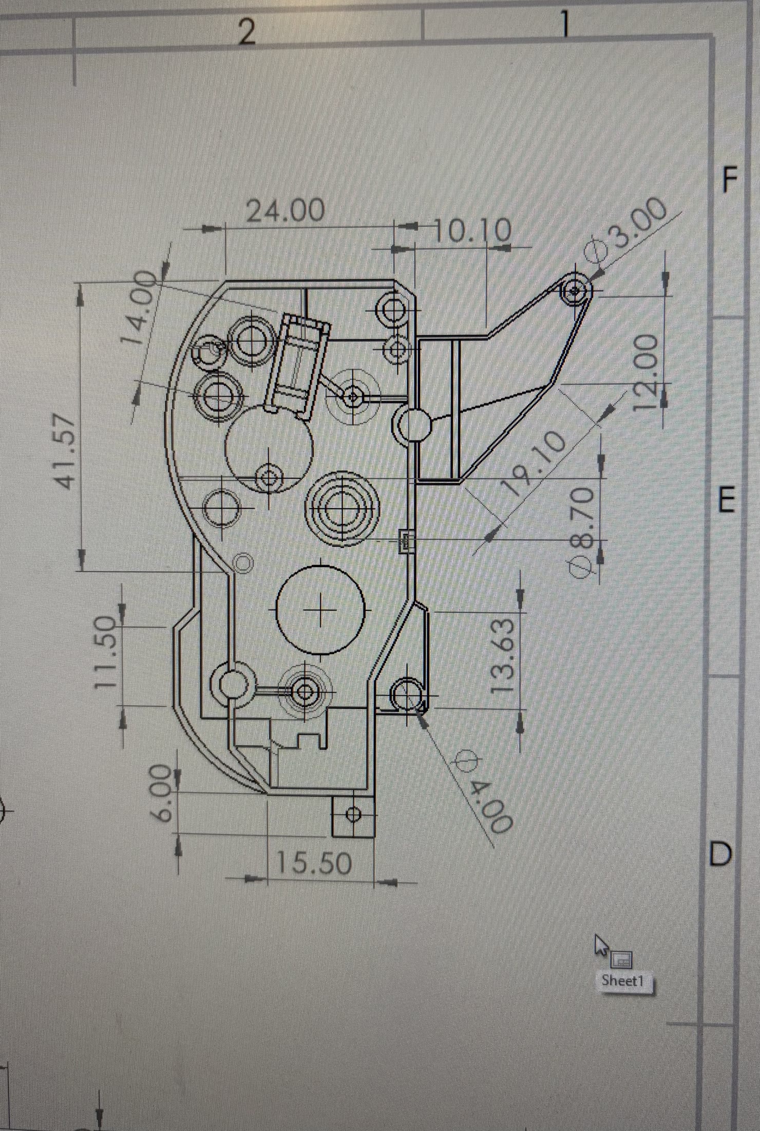
Engineering drawings were created for each part, with the dimensions and tolerances needed to manufacture the components directly from the drawings.
Measurement and verification
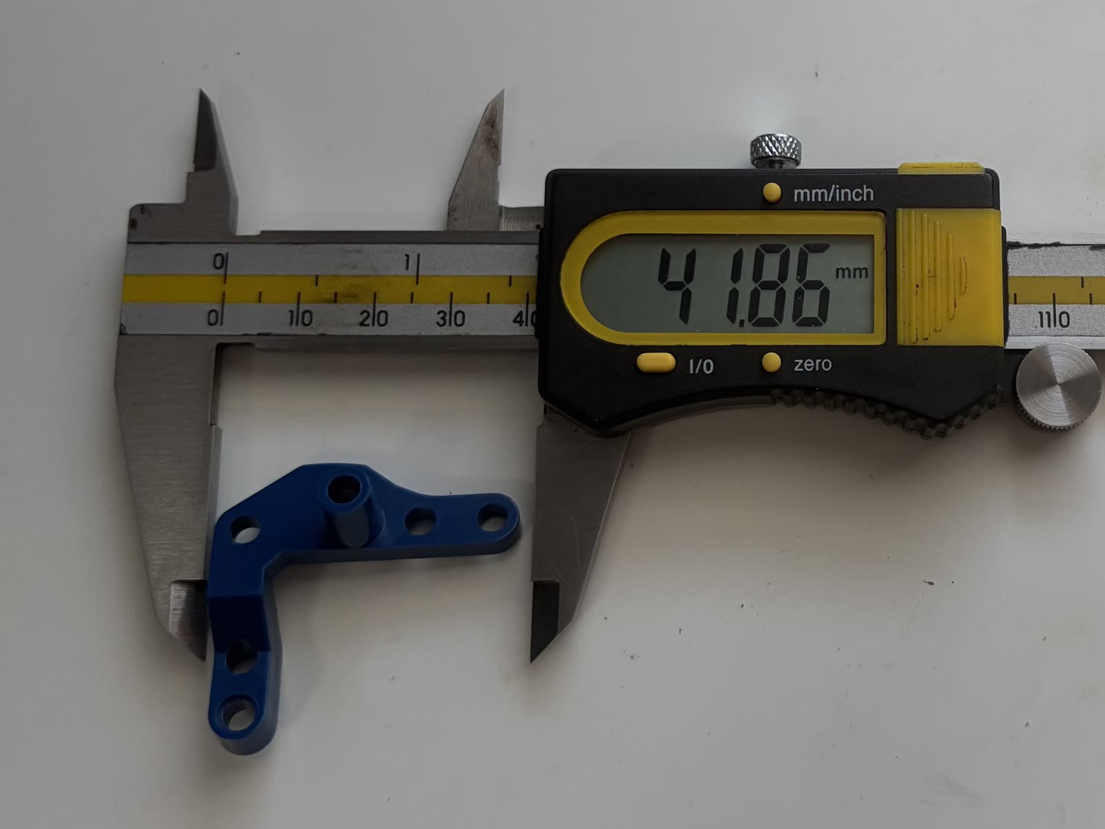
Every dimension in the CAD started as a measurement of the physical part with calipers, then re-checked against the original once modeled. Consistent measurement across the whole team was one of the first things established, so no one’s part would end up slightly off and cause fit issues in the final assembly.
Final assembly
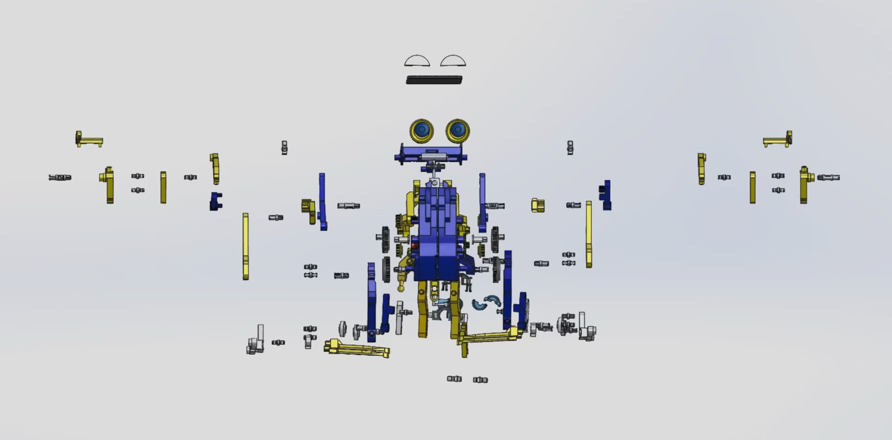
All individual parts brought together into one multi-part assembly with correct mates, mechanical constraints, and motion behavior. Every part fits, every joint articulates through its intended range, and the mechanism walks the way the physical system does.