Project
Autonomous Quadrotor
A custom-built autonomous drone with vision-guided tracking and precision landing, designed as a modular platform for future tool payloads.
Full-stack: autonomy software, electrical integration, and mechanical assembly.
- Python
- MAVSDK
- OpenCV
- YOLO
- ArduPilot
- Pixhawk 6C
- Gazebo Harmonic
- ROS2
- Raspberry Pi
- Linux / WSL2
A three-person team is building this drone from scratch as a modular autonomous platform. My contributions cover the full simulation and autonomy stack and all of the electrical work, along with a good portion of the mechanical build.
Near-term
The near-term milestone is vision-guided target tracking with YOLO and precision landing on an ArUco marker, a scaled-down version of the same rendezvous and docking problem that space and industrial robotics teams solve at much larger scale.
Long-term
The long-term vision is a swappable tool mount system using GX-series connectors that lets the same airframe carry different payloads for inspection, agriculture, search and rescue, or delivery.
Development follows a simulation-first workflow. Every autonomy behavior is validated in Gazebo with ArduPilot SITL before being flown on hardware, matching the same iteration loop used across autonomous vehicle development. The finished platform demonstrates a complete stack from mechanical design through electrical integration through onboard perception, decision-making, and control.
Simulation demo
The entire autonomy stack is developed and validated in simulation before touching hardware. Gazebo Harmonic runs the physics and camera rendering, ArduPilot SITL runs the exact same flight control firmware that flies the real drone, and the Python autonomy code connects to it over MAVSDK, the same way it will connect to the physical Pixhawk. The sim environment includes a custom drone model with a downward-facing camera calibrated to match the planned hardware, plus a moving target with an ArUco marker attached. This makes it possible to iterate on tracking logic, coordinate frame handling, and landing behavior in a shorter time frame with zero crash risk.
Software stack
The autonomy stack splits perception across two compute nodes and coordinates them through asyncio on the flight controller. The design keeps latency-critical work close to the flight loop while offloading heavy inference to more powerful hardware, following the same architectural pattern used on production autonomous drones.
Stack breakdown
Raspberry Pi: Camera hub
The Raspberry Pi receives the live feeds from both onboard cameras. It keeps both feeds available for local processing and streams them over Wi‑Fi to the laptop for YOLO-based object detection.
Onboard marker detection
OpenCV runs directly on the Raspberry Pi to detect ArUco markers and estimate their position and orientation relative to the drone. This stays onboard because landing needs fast responses; relying on a Wi‑Fi connection for this step could add delays that reduce landing accuracy.
Object detection: YOLO
The laptop runs Ultralytics YOLO with VisDrone weights on the camera feeds sent by the Raspberry Pi. It detects relevant targets and sends the resulting bounding boxes back over Wi‑Fi. Running YOLO on the laptop avoids overloading the Raspberry Pi and allows detection to run more smoothly in real time.
Coordination: asyncio + shared mailbox
The software uses asyncio to run camera processing, object detection, and
flight-control tasks at the same time. A shared SharedTarget mailbox
stores the newest detection results, allowing the flight loop to always act on the
latest available target information without waiting for other tasks to finish.
Flight control and simulation
The same control software can send commands to either the real drone or the simulated drone. On the physical platform, it communicates with ArduPilot on the Pixhawk 6C to send flight commands and receive telemetry. In simulation, those commands go to ArduPilot SITL and Gazebo Harmonic instead, letting the system be tested before flying real hardware.
Adding ROS2
The current asyncio setup handles two vision sources and a single target well, but it will become harder to manage as more inputs are added, such as a tool-mounted sensor or LiDAR. What I’m doing with shared state and background tasks is essentially serving the role that ROS 2 is designed to handle natively, which makes moving to ROS 2 a natural next step as the system grows.
Electrical
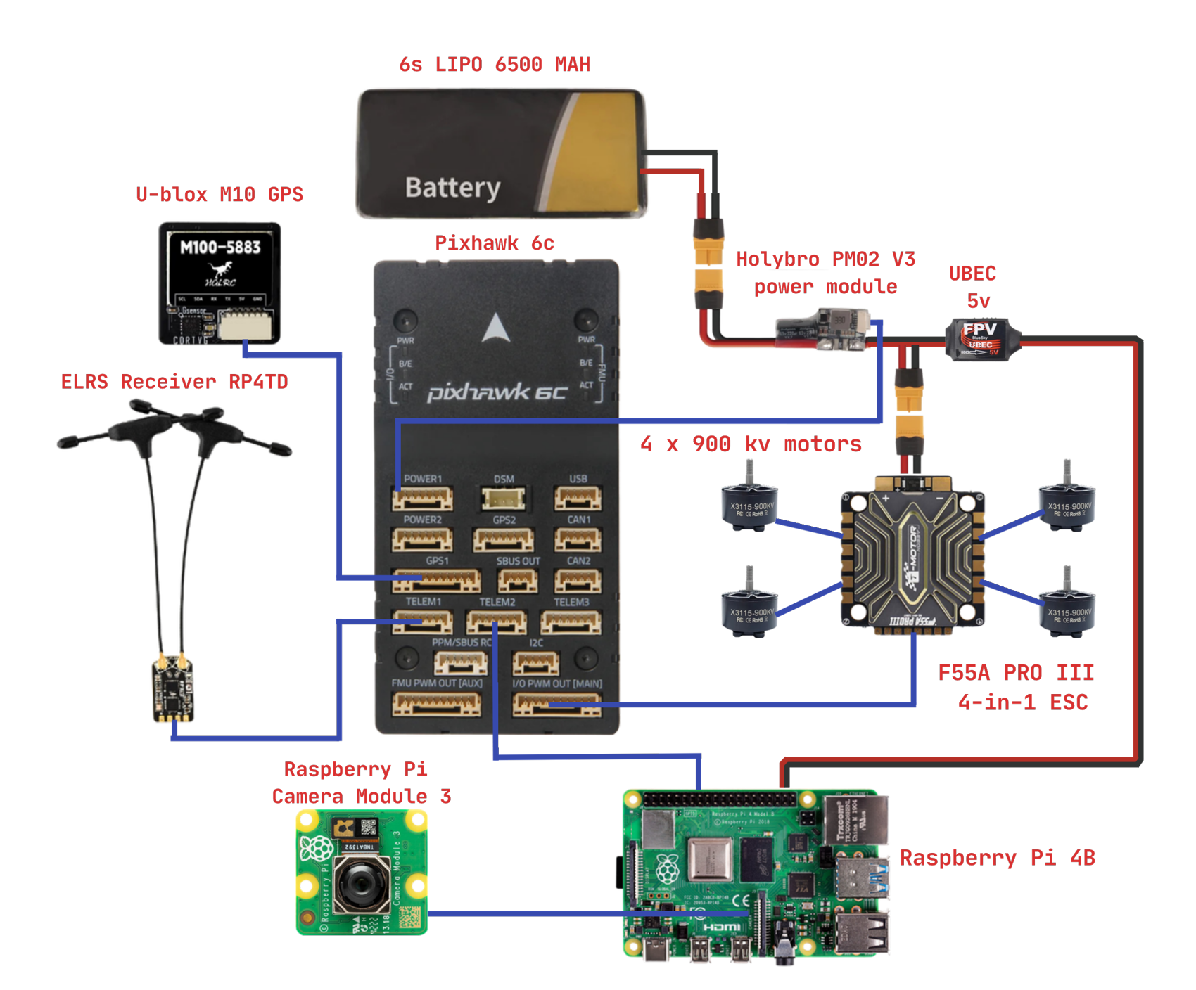
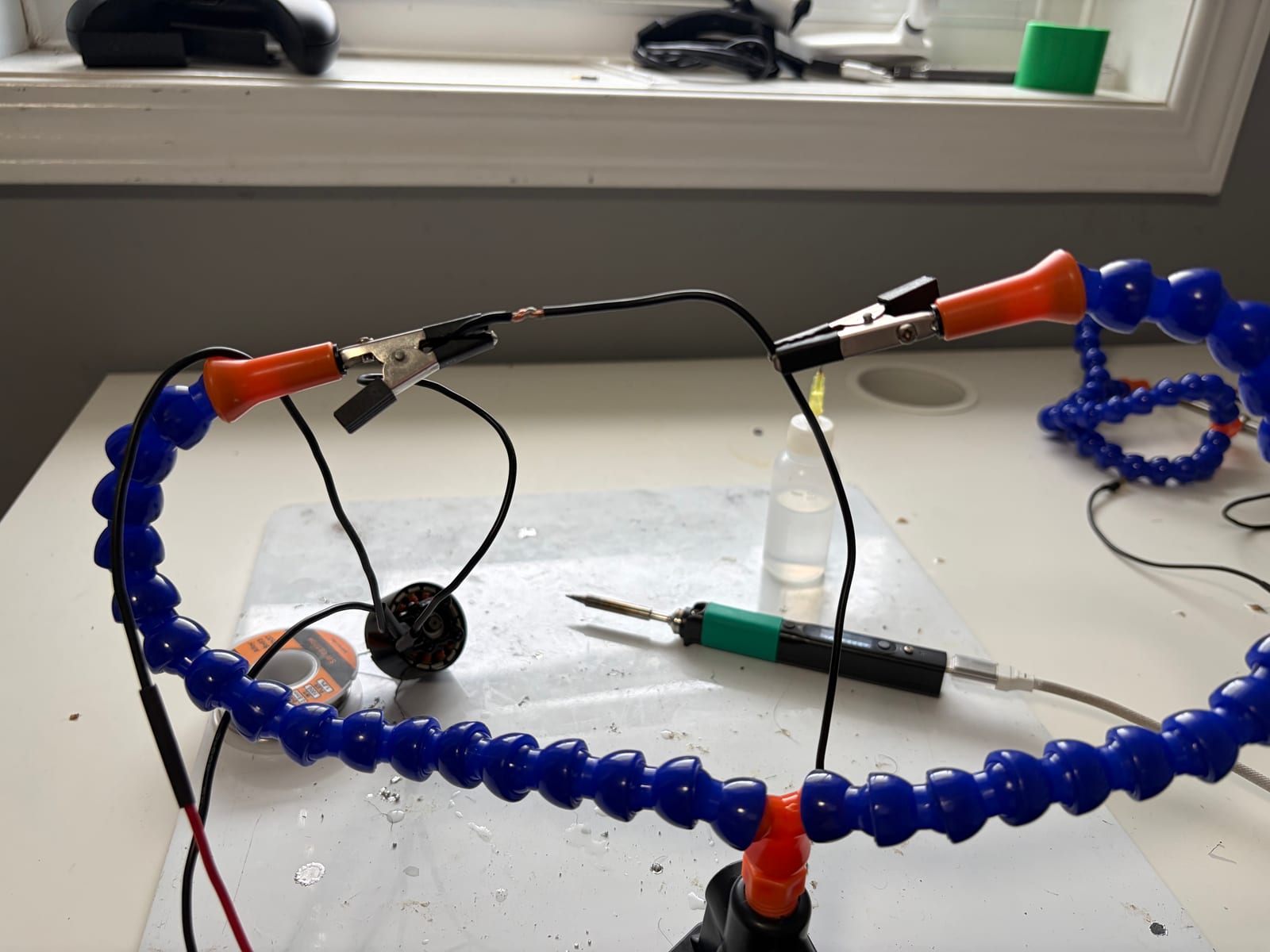
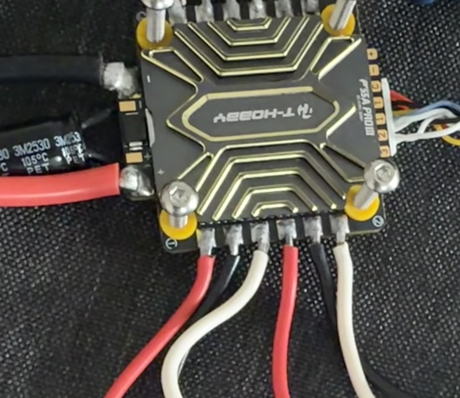
I completed the drone’s wiring and soldering by hand, including motor-to-ESC connections, power connectors, small signal connectors, and repairs to failed joints. The ESC ground connection was the most challenging joint. Its large copper connection pulled heat away from the soldering point, so it took more heat and careful technique to create a clean, reliable joint.
Through the build and testing process, I learned how to produce reliable solder joints, inspect wiring for faults, and troubleshoot electrical issues that appeared during testing and flight.
Debugging: first flight tip over
What went wrong
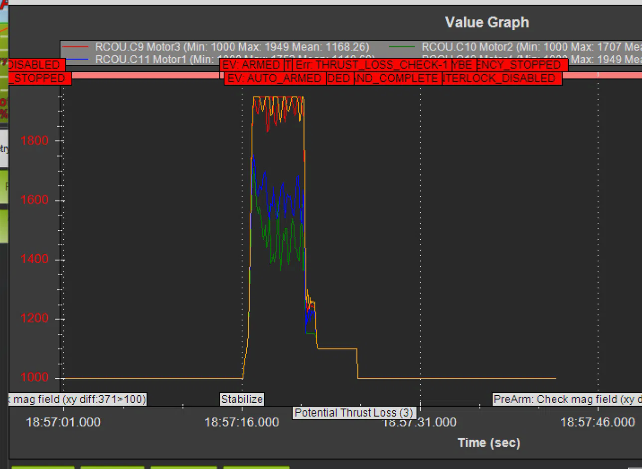
On the first attempted takeoff the drone tipped over immediately instead of lifting cleanly. Pulling the RCOU log off the flight controller showed the story clearly. Two of the four motors were saturating at maximum output while the other two were commanding much lower values, meaning the flight controller was trying to correct an imbalance it could not overcome. This pointed to two separate problems: the motors were not responding fast enough to correction commands, and there was not enough headroom in the system to make aggressive corrections in the first place.
Fix
Two changes solved it. First, switching motor output from analog PWM to DShot600 gave the ESCs much faster and more consistent response to setpoint changes, so corrections that used to lag now happen within a single control loop. Second, upgrading the power system from 4S to 6S nearly doubled the theoretical thrust-to-weight ratio, giving the flight controller real headroom to make aggressive corrections during takeoff instead of maxing out just trying to hover.
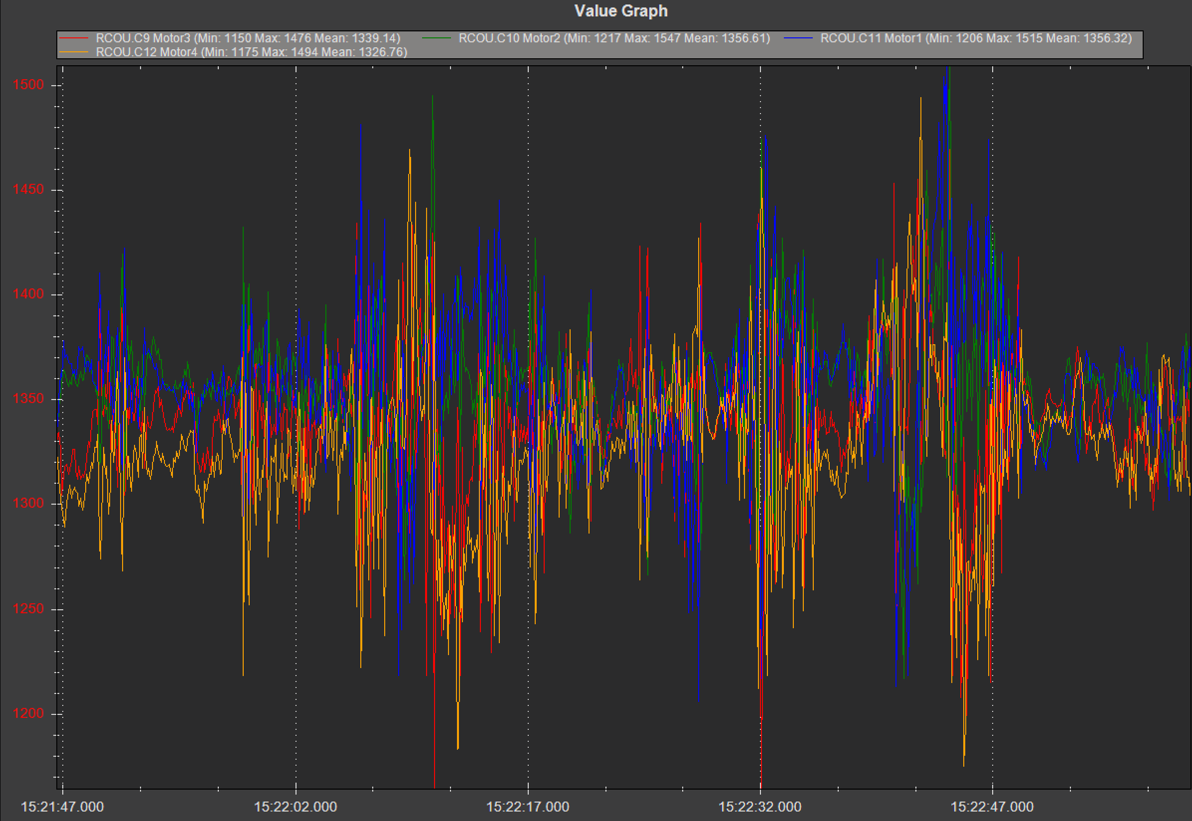
After the fix, all four motor outputs sit close together and stable, with plenty of headroom above and below for the flight controller to correct disturbances. Clean takeoff on the next attempt.
Hardware build & integration
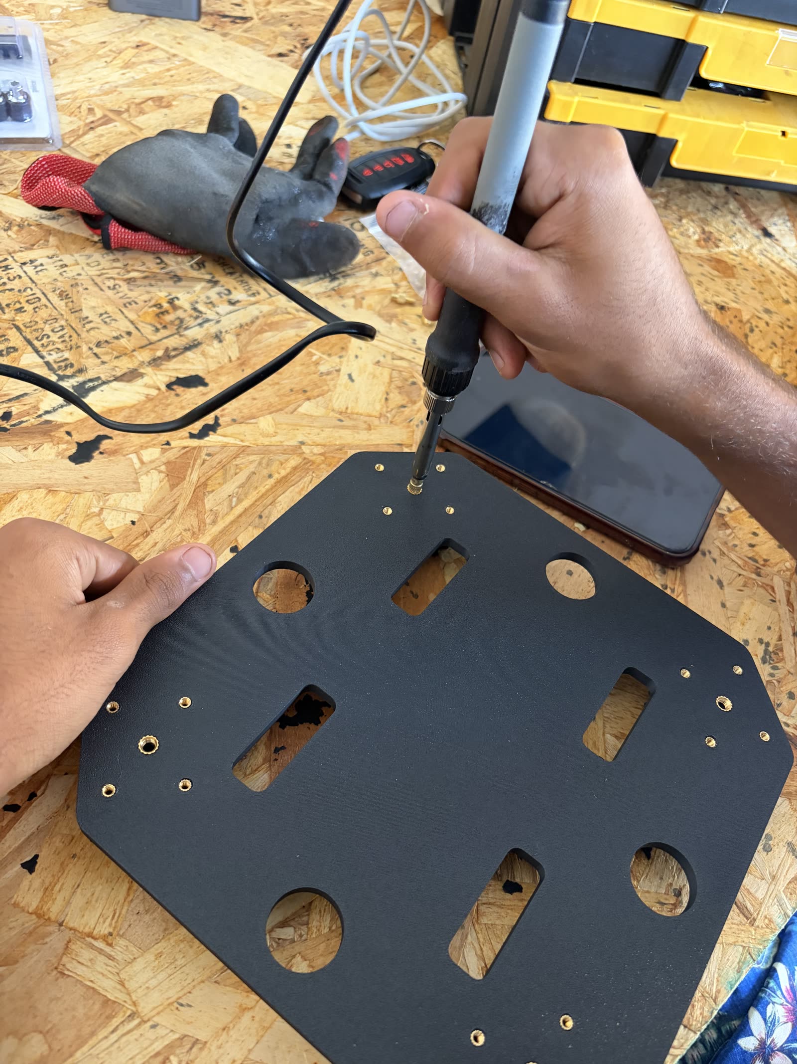
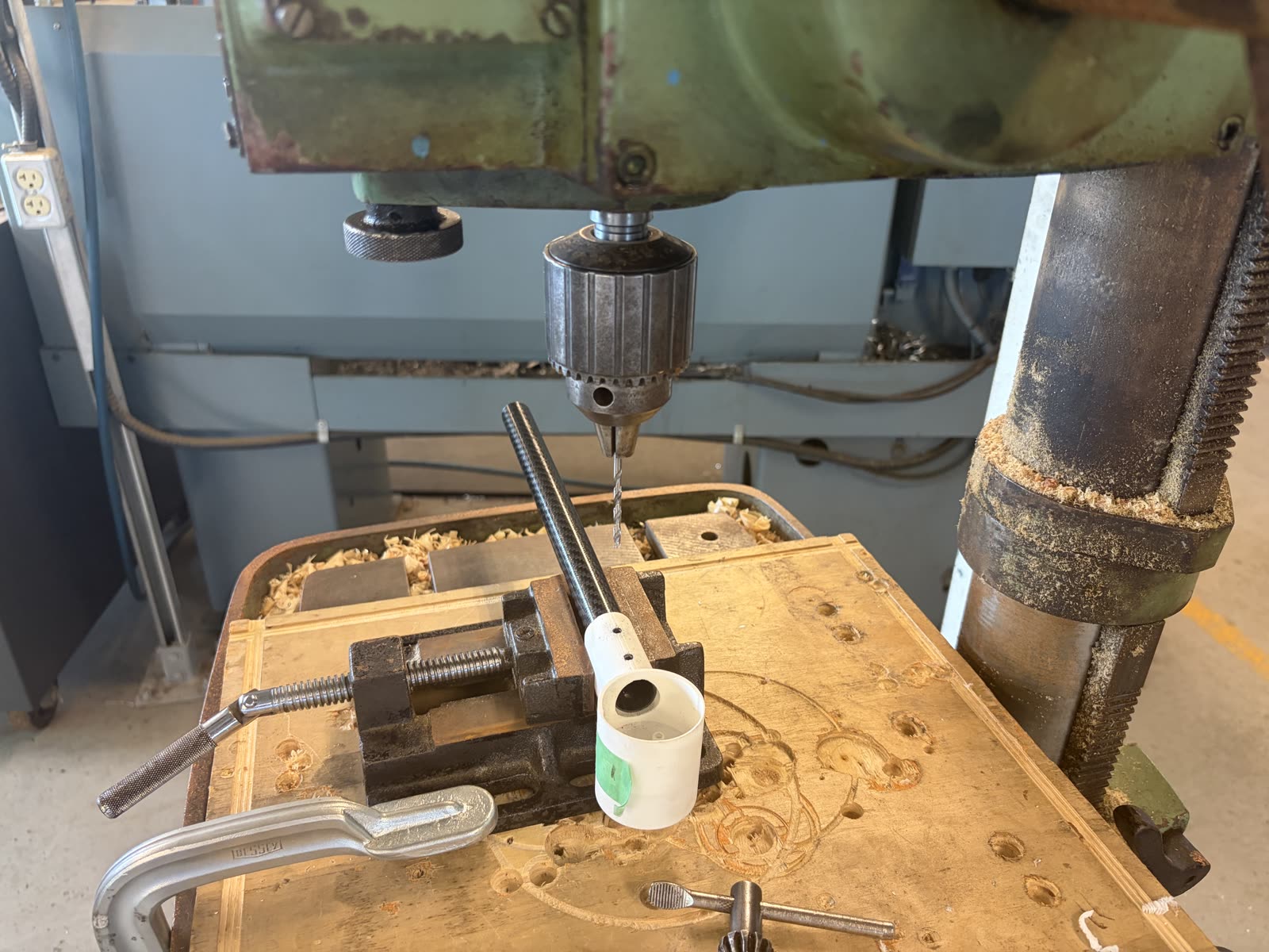
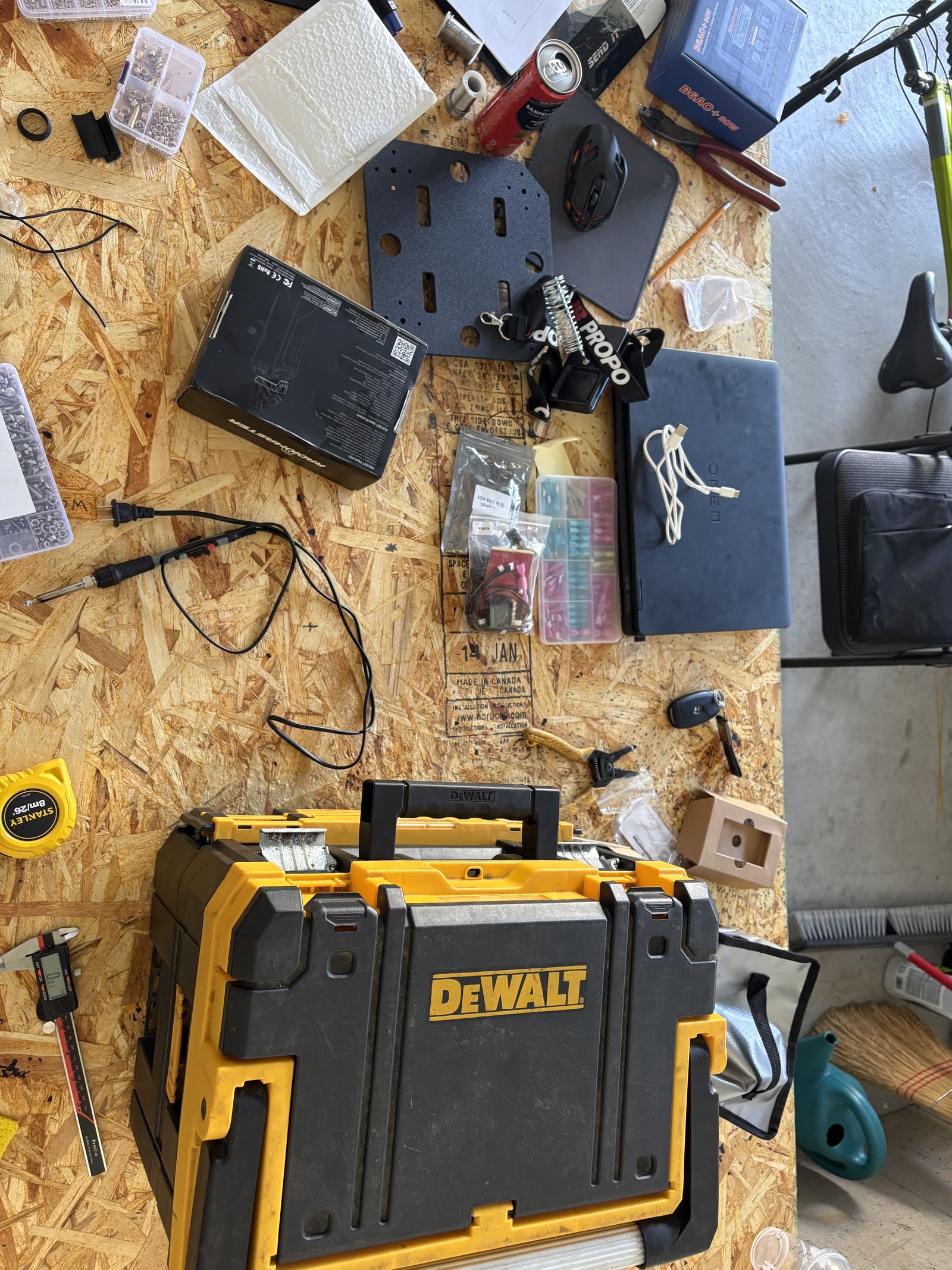
Every mechanical and electrical component on this drone was built by hand. The frame geometry was designed in CAD around the motor mounting pattern, battery size, and camera clearance required by the autonomy system. From there, the parts were 3D-printed, cut, drilled, and assembled into the final frame.